Category

RiAlto Blog

What Is Press Brake Forming? An Engineering & Procurement Guide

What Is Press Brake Forming | Rialto Manufacturing Inc

In precision sheet metal fabrication, a part that deviates by even half a degree can jeopardize an entire mechanical assembly. Press brake forming is the foundational manufacturing process used to shape flat sheet metal into precise, angular profiles. It is the core methodology behind producing everything from simple structural brackets to complex, multi-bend aerospace housings and heavy equipment chassis.

For design engineers, product developers, and supply chain managers, understanding the mechanics of press brake forming is essential for optimizing designs, calculating costs, and ensuring part repeatability.

Whether you’re designing a new product, sourcing fabricated components, or evaluating your sheet metal manufacturing options, understanding how press brake forming works helps improve part accuracy, reduce production costs, and avoid manufacturing issues later in the process.

Core Mechanics of a Press Brake Machine

CNC press brake machine | Rialto Manufacturing Inc

Press brake forming is a force-based process in which sheet metal is bent along a straight axis by pressing it between a matched punch and die set. Modern production environments rely on CNC (Computer Numerical Control) hydraulic or electric press brakes to control the variables involved. During every bending cycle, four key components work together to produce accurate and repeatable bends. 

  • The Punch (Upper Tool): Attached to the moving ram, this profile drives into the sheet metal. The nose radius of the punch directly dictates the inside bend radius of the part.
  • The Die (Lower Tool): The stationary base with a machined groove (typically V-shaped). The width of the V-die opening affects the amount of tonnage required to form the bend.
  • The Ram: The mechanical or hydraulic actuator that delivers controlled force, measured in tonnage (tons per foot), to deform the metal permanently.
  • CNC Backgauge: An automated, multi-axis stops system positioned behind the tooling. The operator presses the sheet metal flat against these gauges before cycling the machine, ensuring the bend line is perfectly parallel and located at the exact dimension required.

Bending Methods: Air Bending vs. Bottoming vs. Coining

Not every sheet metal part is formed the same way. Manufacturers select different bending methods depending on the required tolerances, material properties, tooling availability, and production volume.

Bending Method

Material Interaction Angular Tolerance

Tooling Flexibility

Air Bending The punch touches the metal, but the metal does not contact the bottom of the V-die. The angle is determined strictly by how far the punch descends into the die space.

±1.0° to ±1.5°

High: One set of tooling can form multiple angles simply by adjusting the machine’s stroke depth.

Bottom Bending

The punch forces the material entirely against the walls of the lower V-die, pressing the metal flush against the inner die angle.

±0.5°

Low: The die angle must match the target bend angle precisely (e.g., a 90° bend requires a 90° die).

Coining

High-tonnage stamping where the punch completely penetrates the material’s neutral axis, slightly thinning the metal at the point of deformation.

±0.25°

Very Low: Requires dedicated, high-strength tooling and excessive machine wear; used primarily for critical applications requiring zero springback.

In most manufacturing environments, air bending is the preferred choice because it offers excellent flexibility while reducing tooling costs and setup time. Bottom bending and coining are generally reserved for applications that require tighter tolerances, minimal springback, or highly consistent repeatability.

Material Deformation, Stretching, and Springback

Sheet metal does not behave exactly as shown in CAD models because it experiences both elastic and plastic deformation during bending. One of the most important effects of this behavior is springback, where the material naturally relaxes and slightly opens after the forming force is removed.

The K-Factor and Bend Allowance

When sheet metal is bent, the finished part becomes slightly longer than its original flat pattern because the outer surface stretches during forming. Engineers use K-Factor, Bend Allowance, and Bend Deduction calculations to predict this material movement and produce accurate flat patterns before fabrication begins. The K-Factor identifies the position of the neutral axis within the material thickness. It is one of the key values engineers use to calculate bend allowance and produce accurate flat patterns.

  • K-Factor = t ÷ T

Where t represents the distance from the inside bend surface to the neutral axis, and T represents the total material thickness. Because the metal stretches during bending, engineers calculate the Bend Allowance (BA) and Bend Deduction (BD) to create an accurate 2D flat pattern before laser cutting.

Material Springback

The amount of springback varies depending on the material grade, thickness, and yield strength, making it an important consideration during press brake programming.

  • Low-Yield Metals (e.g., Mild Steel): Exhibit minimal springback (1° to 2°).
  • High-Yield/Work-Hardened Metals (e.g., Stainless Steel, Aluminum 6061-T6): Exhibit greater springback (3° to 5° or more).
  • Correction: CNC software automatically accounts for this by over-bending the part beyond the target design angle.

Design for Manufacturability (DFM) Guidelines

Designing parts with manufacturing limitations in mind helps reduce production costs, minimize scrap, and simplify press brake setups. The following Design for Manufacturability (DFM) guidelines are widely used to improve production efficiency and part quality.

Minimum Flange Length

The flat edge of the sheet metal must span securely across the lower V-die opening during the entire stroke. If a flange is designed too short, it will slip into the die cavity, ruining the part and potentially damaging the machine.

  • Standard Rule: Minimum Flange Length = 4 × Material Thickness (T)

Hole and Slot Proximity to Bends

Placing cutouts, holes, or slots too close to a bend line causes the metal to stretch unevenly. The hole will deform into an oval shape, and the bend line will warp.

  • Standard Rule: Keep the edge of any hole at least (3 × Material Thickness (T)) + Bend Radius away from the center of the bend.

Uniform Bend Radii

Designing a single component with multiple different inside bend radii requires the fabricator to set up multiple different punch-and-die stations on the machine bed. Keeping all inside radii uniform across the part allows the entire run to be completed in a single, efficient setup.

Material Behaviors in Press Brake Forming

Material selection has a direct impact on bend quality, required tonnage, achievable bend radius, and overall manufacturing efficiency.

Even materials with the same thickness can behave very differently during forming. Different alloys demand specialized handling, customized tonnage calculations, and specific minimum bend radii to prevent stress fractures.

  • Carbon/Mild Steel: The most predictable and widely formed material. It accommodates sharp inside radii without fracturing and requires standard production tonnage.
  • Stainless Steel (300/400 Series): Its high tensile strength requires approximately 50% more bending tonnage than mild steel. Because stainless steel work-hardens quickly, it also requires larger inside bend radii to help prevent cracking along the grain direction.
  • Aluminum (e.g., 5052 vs. 6061): 5052-H32 is highly ductile and forms easily. Conversely, structural 6061-T6 is highly brittle; if formed over an inside radius that is too sharp, the outer bend radius will develop micro-fractures and fail structurally.

Below are answers to some of the most common technical questions engineers, designers, and procurement professionals ask about press brake forming.

Frequently Asked Questions 

How do you determine the required press brake tonnage for a specific material?

Tonnage is calculated based on material thickness, tensile strength, and V-die width using the formula: P = (K × S × T²) ÷ V. Increasing the V-die opening reduces the required bending force but results in a larger inside radius.

Why do identical parts from the same production run show slight bend angle variations?

Slight bend angle variations are typically caused by normal mill thickness tolerances (even a 0.05 mm difference) and changes in the material’s grain direction. Both factors affect how the metal responds to bending and springback, resulting in small-angle variations between otherwise identical parts.

Can you form a precision bend right next to a laser-cut hole without causing distortion?

Standard tooling may distort holes into an oval shape if they are positioned closer than (3 × Material Thickness) + Bend Radius to the bend line. To prevent distortion, fabricators can use specialized rotational wing dies or incorporate relief slots into the design to isolate bending stresses.

How does grain direction affect structural sheet metal bending?

Bending perpendicular (across) the material grain ensures maximum structural strength and prevents cracking, while bending parallel (with) the grain requires less tonnage but highly increases the risk of the outer radius splitting.

What is the fundamental difference between a Press Brake and a Folder (Leaf Brake)?

A press brake uses a vertical ram to press a punch into a stationary die (best for high-tonnage, heavy-gauge parts), whereas a folder clamps the sheet flat and swings a pivoting beam upward to bend the edge (best for large, thin-gauge panels).

Technical Project Review

Successful press brake forming depends on more than selecting the right machine. Material Standard formulas and general rules are a great starting point, but real-world material behaviors can vary. To avoid unexpected tolerances or tooling limitations during your next production run, early collaboration is key.

Before finalizing your CAD layouts, feel free to leverage our technical expertise. At Rialto Manufacturing Inc, we act as an extension of your engineering department to review bend allowances, hole proximities, and material selections, helping you reduce scrap and cycle times.

How Industrial Laser Cutting Works: A Technical Overview

Industrial Laser Cutting | Rialto Manufacturing Inc

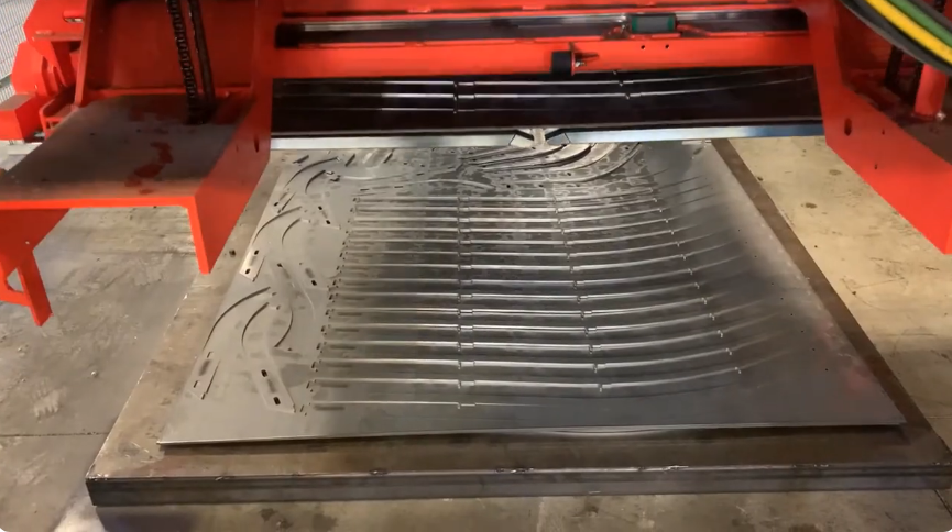
At its core, industrial laser cutting is a highly precise thermal fabrication process that uses a concentrated, computer-controlled laser beam to melt, burn, or vaporize material along a programmed path. Because it is a completely non-contact process, there is zero physical tool pressure, ensuring exceptional accuracy without material distortion or blade wear. Achieving this level of accuracy requires specific precision cutting capabilities that depend entirely on the setup. But how exactly does a beam of light achieve enough power to slice through heavy metal instantly?

But how exactly does a beam of light achieve enough power to slice through heavy metal instantly, and how does it translate a digital drawing into a flawless physical part?

Understanding how industrial laser cutting works starts with recognizing why the technology has become a manufacturing standard. It combines speed, precision, and design flexibility in ways that traditional cutting methods cannot match. This overview breaks down the process step by step, from beam generation to final part quality.

What Is Industrial Laser Cutting?

So, what is industrial laser cutting, exactly? It is a thermal fabrication process that uses a concentrated beam of light to melt, burn, or vaporize material along a precise, programmed path. Unlike mechanical cutting, it is a non-contact process, meaning the material experiences no physical tool pressure or blade wear.

This distinction matters because non-contact cutting reduces distortion and keeps tolerances consistent across long production runs.

How the Industrial Laser Cutting Process Works


The industrial laser cutting process follows a repeatable sequence: a laser beam is generated, focused through optics, and directed onto the material surface along a CNC-controlled path. As the beam moves, it melts or vaporizes material in a narrow line called the kerf.

  • The beam is generated and amplified inside the laser source.
  • Mirrors and lenses direct and focus the beam onto the material.
  • An assist gas clears molten material from the cut.
  • The cutting head moves along a pre-programmed path to complete the part.

Each step depends on the previous one, which is why consistency at the source directly affects the final cut.

Laser Beam Generation: The Science Behind the Cut

Laser beam generation begins inside a lasing medium, most commonly a doped optical fiber in modern industrial systems. Energy is pumped into this medium, exciting particles that release photons, which then bounce and amplify inside the fiber core.

This amplified light exits as a highly stable, high-intensity beam. When focused into a very small spot, this beam achieves a power density high enough to melt or vaporize metal almost instantly, which is the core principle behind the entire cutting process.

From CAD to CNC Manufacturing: The Complete Workflow

Every laser-cut part follows a structured path from CAD to CNC manufacturing before any cutting occurs.

  • Design: The part is modeled in CAD software with exact dimensions and geometry.
  • Programming: CAD data is converted into CNC toolpaths defining speed, sequence, and cutting order.
  • Setup: Material is loaded, secured, and matched against the programmed thickness and type.
  • Calibration: The machine sets focus height and reference position for accuracy.
  • Execution: The laser cuts the part exactly as programmed, often with automated material handling.

This workflow is why laser-cut parts remain dimensionally consistent from the first unit to the last.

Factors That Affect Cutting Quality

Several cutting quality factors work together, and adjusting one often requires rebalancing the others.

  • Material thickness determines how much energy and time are needed for full penetration.
  • Laser power must match thickness; too little causes incomplete cuts, too much widens the kerf.
  • Cutting speed affects edge finish; too fast leaves dross, too slow increases heat damage.
  • Focus position controls kerf width and edge straightness.
  • Assist gas type influences oxidation and how cleanly molten material is expelled.

Each factor exists because the cutting process is a balance of heat, speed, and material removal happening in milliseconds. At Rialto Manufacturing Inc, we use state-of-the-art Fiber Laser Machines that can cut up to 20mm Carbon Steel and 12mm Stainless Steel with extreme precision.

Best Metals for Precision Cutting

Not every metal responds the same way to a laser beam, which is why material selection matters for precision cutting.

  • Carbon steel cuts efficiently, often using oxygen assist gas for thicker sections.
  • Stainless steel produces clean, oxide-free edges with nitrogen assist gas.
  • Aluminum is reflective and conducts heat quickly, requiring higher power for consistent results.
  • Copper and brass are highly reflective, making them more difficult and often requiring specialized settings.

Materials with higher reflectivity and conductivity generally demand more precise parameter tuning to achieve a clean cut.

Understanding Laser Cutting Accuracy

Laser cutting accuracy comes from the combination of a small, controlled beam spot and CNC-guided motion. Because the beam interacts with only a tiny area at a time, there is minimal material deflection compared to mechanical cutting tools.

Repeatability is equally important: the same CNC program produces the same result across hundreds or thousands of parts, which is why tolerances hold steady across full production batches.

Industrial Manufacturing Applications of Laser Cutting

Laser cutting supports diverse industrial manufacturing applications because it adapts easily to different thicknesses, geometries, and volumes.

  • Automotive: brackets and structural components requiring tight tolerances.
  • Agriculture: panels and parts built to withstand mechanical stress.
  • Construction equipment: heavy-gauge plate requiring dimensional consistency.
  • Electrical components: precise cutouts for enclosures and panels.

These industries rely on the process because design changes require no new tooling, unlike stamping or punching.

Role of Laser Cutting in Industrial Manufacturing Technology

As industrial manufacturing technology continues to evolve, laser cutting remains central because it bridges digital design directly to physical production. CAD files translate into finished parts with minimal manual intervention, reducing variability introduced by manual processes.

This direct digital-to-physical link is also why laser cutting integrates smoothly with automated production lines and Industry 4.0 manufacturing environments.

Frequently Asked Questions

How is a laser beam generated? 

A laser beam is generated by pumping energy into a lasing medium, such as a doped optical fiber, which amplifies light into a concentrated, high-intensity beam.

What affects laser cutting accuracy?

Laser cutting accuracy is affected by the focus position, cutting speed, laser power, and CNC program precision, which work together consistently.

Which metals are best for laser cutting? 

Carbon steel and stainless steel are best for laser cutting due to predictable melting behavior and clean, consistent edge quality.

Can laser cutting handle complex CAD designs? 

Yes, laser cutting handles complex CAD designs easily because the cutting path is generated directly from digital geometry rather than from physical tooling.

Why is CNC programming important in laser cutting? 

CNC programming is important because it converts CAD data into exact toolpaths, ensuring repeatable accuracy across every part produced.

Bringing Precision to Your Next Project

Industrial laser cutting works by transforming concentrated light into precise, controlled heat guided by CNC programming and CAD-derived toolpaths. From beam generation to material selection, every stage contributes to the accuracy and repeatability that manufacturers depend on. At RiAlto Manufacturing Inc, we are always ready to help you navigate these technical complexities, whether you need to refine a design or scale production. Our team is here to support your manufacturing goals with reliable, precision-focused solutions.

Metals in Manufacturing: Balancing Strength, Durability, and Cost

Metals in Manufacturing | Rialto Manufacturing Inc

Selecting the right material is one of the most critical decisions in the production process. Choosing the wrong metal can lead to premature product failure or cause manufacturing budgets to skyrocket. When evaluating metals in manufacturing, engineers and product designers must strike a perfect balance between three core pillars: metallurgical strength, long-term durability, and raw material costs.

Continue Reading

How to Handle Manufacturing Growth Without Adding Costs

how to increase manufacturing capacity | Rialto Manufacturing Inc

Every manufacturing company dreams of growth. But when a Tier 1 supplier experiences a sudden surge in demand, that dream can quickly turn into an operational nightmare. You want to scale, but you are hitting a physical and financial wall: there is no extra floor space on your production floor, your machinery is already running at maximum capacity, and skilled labor is harder than ever to find.

Continue Reading

How Custom Metal Fabrication Streamlines Your Production Process

Custom Metal Fabrication | Rialto Manufacturing Inc

In the manufacturing sector, efficiency isn’t just a goal; it’s the dividing line between scaling up or falling behind. To optimize an assembly line, operations managers frequently audit workflows, upgrade software, or retrain staff. However, the most significant production breakthroughs often come down to a fundamental hardware choice: switching from rigid, off-the-shelf parts to tailored components.

Continue Reading